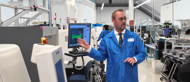
In electronics manufacturing, many of the most common delays can be traced back to gaps or ambiguities in documentation. Even with a highly experienced manufacturing partner, a successful build depends on clear and detailed communication. When there are misalignments during the project handoff, it can result in inaccurate timelines, unexpected build issues, delays during testing, and added time spent on revisions. This is especially important for complex assemblies, where precision and clarity in the early stages have a direct impact on production speed and final product quality.
To help accelerate your build and ensure a smooth transition from engineering to production, we recommend preparing these seven key documents. That said, if you’re missing any of them, don’t worry. Our team is here to help you fill in the gaps and move your project forward with confidence.

These are the recommended files that we look for in our quoting process.
1. CAD Drawing
The CAD drawing is the primary design file that includes netlists, layer details, and the electrical layout. It plays a key role in BOM validation, design for manufacturing analysis (DFM), and toolpath generation. Providing your CAD files allows us to carefully review your design and offer practical suggestions during the manufacturability analysis to identify potential issues early and optimize the design for faster, more reliable production. We also use the CAD file to create a digital version of the board in our MES software, enabling us to prepare clear instructions for our production team with correct orientation and polarity, and to track production progress digitally at every stage.
2. Bill of Materials (BOM)
The BOM details all components, quantities, and specifications necessary for assembly. It plays a crucial role in validating parts against the design, facilitating procurement planning, and ensuring accurate assembly. Providing a complete and precise BOM helps prevent sourcing errors and supports efficient production scheduling. Dorigo Systems also provides a BOM health report to highlight any potential obsolescence or long lead times, helping you mitigate risks early in the process.
3. Assembly Drawings
Assembly drawings provide a visual reference for how components are to be placed on the board. They should include component outlines, polarity markings, reference designators, and any mechanical details not evident in the CAD data. These drawings are used by the assembly team during both placement and inspection. Having clear, complete assembly drawings allows our team to verify orientation, placement accuracy, and special instructions, reducing the risk of errors or delays during production.

Having the right files helps avoid delays in the SMT pick and place process.
4. Gerber Files
Gerber files are the standard outputs used by PCB fabricators to manufacture the board. They contain visual data for each layer, including copper traces, solder mask, silkscreen, paste, and the board outline. These files are generated from CAD data and serve as direct inputs for the photo plotting and CAM processes. Including mechanical layers and a detailed stack-up drawing with material specifications, layer order, copper weights, and overall board thickness helps ensure the board is built accurately. A complete Gerber package eliminates ambiguity during fabrication and supports a smooth transition into production.
5. 3D Model of Mechanical Parts and Mechanical Drawing
A STEP model of key mechanical components helps verify fit and alignment during the design for assembly review, especially when the PCB interfaces with enclosures, heatsinks, or other mechanical systems. The mechanical drawing provides the full context of the assembly, including board outlines, mounting features, connector locations, and enclosure mating surfaces. Together, these files provide us with the necessary mechanical details to accurately plan assembly and testing, reducing errors and speeding up time to market.
6. Test Procedure, Specifications, and Test Duration
Test procedures include detailed steps, expected results, tolerances, and test point access to guide our test engineering team in building or adapting fixtures for reliable and consistent functional testing. Providing test duration per unit allows accurate estimation of how many units can be tested within a given timeframe and balances the production line to avoid bottlenecks or delays.
7. Keep-Out Drawing
Keep out drawings show areas on the PCB where copper, components, or routing should not be placed. These zones are important for mounting holes, mechanical clearances, and high-voltage isolation. Missing or unclear keep-out drawings can cause physical interference or regulatory compliance problems.
Why Documentation Matters, and What to Do Next
Having thorough, well-organized documentation allows your Contract Electronics Manufacturer (CEM) to move efficiently through quoting, assembly, and testing. Preparing these files early helps minimize potential issues and ensures a smoother transition into production.
At Dorigo Systems, we understand that it’s not always possible to have every document ready up front. That’s why we work closely with OEMs to identify what is needed and guide you through every step of the process. Our goal is to ensure a seamless transition from design to production, whether you have everything in place or are just getting started. Get in touch with our team at sales@dorigo.com to discuss your documentation package and how we can support your success.
Join the Dorigo community on LinkedIn to explore the latest advancements in electronics manufacturing.

